This article was originally written in 2018 and there have been many updates to Azure Sphere between then and now so some changes may be required. I thought it would be useful to share this as-is (and the code) in case it was of use to others who wanted to take advantage of an ultrasonic sensor and the Azure Sphere development kit.
Azure Sphere is a secure microcontroller (MCU) development kit that is designed to work with Azure IoT services. This project demonstrates how it could be used to remotely manage a parking garage. It uses an ultrasonic sensor to detect the presence of a vehicle. By sending data back to Azure IoT Hub, an operator can remotely see which parking spaces are occupied. The sensor will also be used to assist the driver when parking the vehicle by providing a traffic light system to indicate when it is neatly parked.
What we’ll need
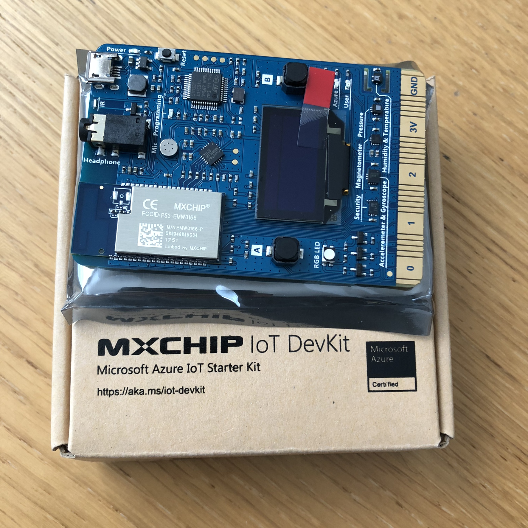
This solution uses the Azure Sphere MT3620 Development Kit, the MT3620 Grove Shield, and a Grove Ultrasonic Ranger.
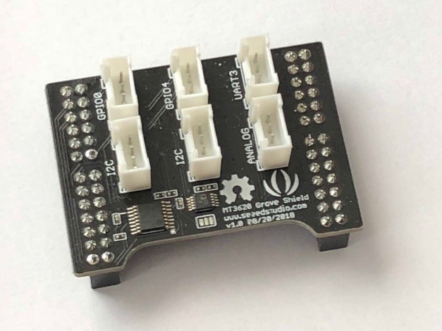
The shield has six Grove compatible connectors with two GPIO ports, two I2C, one analogue, and one serial UART. It has a small cut-out section to provide access to the buttons on the MT3620 board, which helps with orienting it when assembling.
Before starting this build, you should have set up the Sphere development kit and deployed a basic Azure IoT Hub template app to ensure that everything is configured correctly with the device.
Assembling the parts
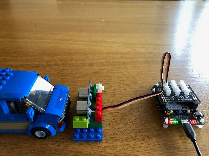
The Grove Shield for the MT3620 attaches to the two header rows on top of the board. The standard Grove cable for the ultrasonic ranger clips into GPIO0 on this shield and the other end clips into the ranger board. For purposes of testing, we’ll have the board connected via USB for power and debugging. The board can also be powered by a dedicated 5V power supply.
Programming for Azure Sphere
Code for Azure Sphere is written in C. Because Sphere is built around a custom Linux core, it supports a number of standard POSIX APIs and a set of standard headers are added with the standard project template. The Sphere SDK contains an API for working with GPIO pins along with a Logging API that can display output in the Visual Studio debug output window. You can scan for Wi-Fi and change settings via a dedicated API or use the azsphere command-line tools from a development machine. Each open resource is represented by a File Descriptor, a unique handle that must be closed to allow the resource to be reused. The Sphere Dev Kit includes 76 GPIO pins on the header that can be used for input or output. A pair of built-in buttons and four RGB LEDs are also represented by GPIO pins.
Each Sphere application has an application manifest where you declare ahead of time what features you require access to. If you don’t specify each GPIO you will use in this file, the GPIO_OpenAsOutput or GPIO_OpenAsInput call will fail with error EACCES.
Using the ultrasonic sensor
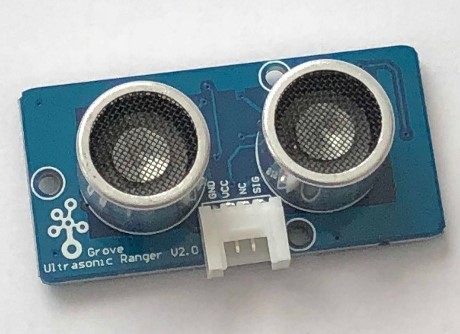
The ultrasonic sensor used here is designed for the Grove modular system, but you can also get ones that are wired manually. It has two devices that look like speakers. One transmits an ultrasonic pulse; the other is a receiver. The sensor allows you to measure the distance to an object from the time it takes for the pulse to leave the transmitter and bounce back to the receiver. The specification says it can measure up to 4 meters. This is more than enough to monitor a parking space. In prototyping, I found that it is accurate down to about 2 cm, which is just right for this scenario because we want the driver to leave at least a 2 cm gap between their car and the wall!
The programming model of Sphere is quite basic and doesn’t support interrupts, so you have to poll to check for a signal. In fact, it’s awkward, because there is a single pin used to send a pulse and measure the response. You have to open the pin, raise the voltage high for 10 microseconds, then close the pin so that you can use it again as an input.
In order to time the duration of the ultrasonic pulse, we have to measure the time taken from the input pin first going high to when it drops back to low again. This can be done by calling clock_gettime at these points and then subtracting the start time from the end to get the duration in nanoseconds. We know that sound takes approximately 29 microseconds to travel a centimetre, so the ping travels to the object and back in double this time, 58 microseconds. Because our readings are in nanoseconds, this equates to 58,000 ns. We can divide our duration reading by 58,000 to return a result in centimetres.
Build a traffic light
We’re using this measurement for two things. First, locally it helps the driver via a traffic light system. To do this we need to define thresholds for when to change the light state between red, amber, and green. I’ve tested the code with a toy car so I’ve scaled down these values, but they are easy to change. Below 2 cm the light is red to warn the driver to stop, between 2 cm and 8 cm the amber light is shown to warn the driver to use caution, and beyond 8 cm the green light is shown.
The Azure Sphere Dev Kit has four RGB LEDs built in. Each LED has three digital channels that allow for seven possible colours. Each channel of each LED is a separate GPIO pin on the board. To make a traffic light we must be able to turn on just red, just green, or both red and green to make yellow. The IoT Hub project template for Sphere adds the led_blink_utility.c file with helper functions to simplify development with the RGB LEDs.
The secondary use for the sensor is to report the occupied status of the parking spot to a cloud service. For simplicity, we will define this as when in amber or red states, because this indicates there is a car currently parked or manoeuvring in the space. This value will be sent to IoT Hub as a device twin property.
Talk to Azure IoT Hub
Right click on References and select Add Connected Service. Here you can select an Azure account and specify either the Azure IoT Hub instance or Device Provisioning Service. This will generate some code files for the project, allowing you to interact with IoT Hub. Whenever you want to report back the occupied status of the parking space to IoT Hub, you call AzureIoT_TwinReportState. You only need to send this when the state changes and not every time you take a measurement. The azure_iot_utilities.c file also contains functions to send messages and attach handlers to incoming commands or device twin requests.
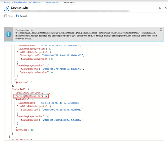
The raw JSON containing the device twin properties is displayed in the Azure portal along with the timestamp of when the property was last changed.
Call to action
The Azure Sphere SDK contains useful template projects for connecting to Azure IoT Hub and controlling onboard LEDs. By connecting external peripherals, either through the Grove Shield or using the header pins directly, you can put together powerful solutions and connect sensors and outputs securely to your IoT infrastructure. Download the full code used for the Ultrasonic Ranger